
Position Analysis of a 4 Bar RPRR Grashofian Inverted Slider Crank Rocker Mechanism 
Procedure
In this experiment you will guided through the position analysis of a 4 bar RRPR Grashofian Inverted Slider Crank. Position analysis can be approached analytically. Using complex numbers is a popular analytical approach. The animated guide that follows right next shows the analytical method of determining the position of a point on the coupler of a RRPR linkage as the linkage moves. The next animation shows the graphical constructions needed for the position analysis of a double crank linkage. A summary of what you are expected to do follows. This is followed by stwo animated guides for finding out the two extreme configurations for the slider, because in a slider crank, while the input link (link 2 - crank) does rotate through a full circle, the slider has limits on its displacement. There are thus two extreme positions of the slider and the corresponding crank angles that you are expected to find out using these guides.
- In the Instruments tab use the first applet to choose a set of 4 link lengths. Enter your choices for link lengths. The apllet will let you know if the lengths conform to a Grashofian Double Crank. If your link lenths are improper go back to the Introduction tab and check the Crashofs criteria Grashofian Double Crank and modify link lengths accordingly.
- Use the Drawing Board applet in the Instruments tab to find the linkage configuration for a given input link orientation (theta 2).
- Finally there is a third applet in the Instruments tab which lets you verify your results. Enter your answers to see the correct values for coupler position and the accuracy of your answers obtained graphically.
The following are animated guides for analytical and graphical methods of position analysis for a 4 bar RRPR Grashofian Inverted Slider Crank.
Position Analysis of a RRPR Linkage Using Complex Numbers
Graphical Position Analysis of a RRPR inverted slider crank linkage
Finding extreme positions of a RRPR inverted slider crank linkage using complex numbers
Finding extreme positions of a RRPR inverted slider crank linkage graphically
Instruments
Choose link lengths, preferably keeping them within 10 units length for easy viewing of animations. Enter them and a coupler arm length and orientation of your choice in the following applet in the designated text boxes. Link 1 represents the ground link. Press the Enter button to verify if your data conforms to a Grashofian Inverted Slider Crank. Note that coupler arm length and orientation play no role in Grashof's criteria, but you are merely asked to enter them for use in later stages. In case you get a message stating that your data does not conform to a Grashofian Inverted Slider Crank.
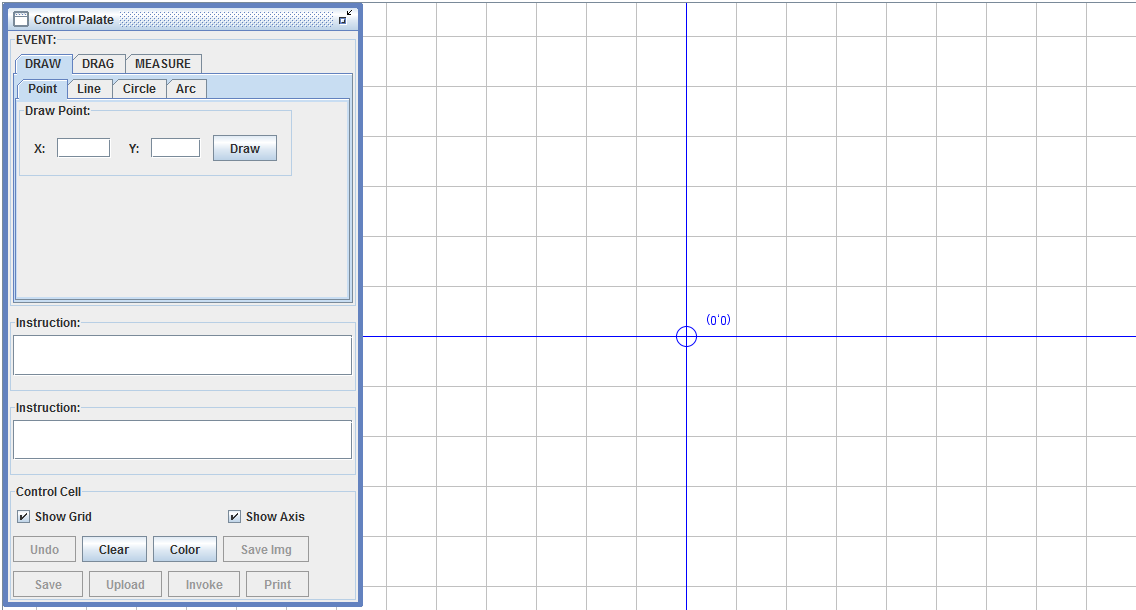
Once your link lengths are validated, you are expected to find out graphically the position of the coupler point for a crank orientation of your choice and alo thehe limiting positions of the slider using the Drawing Board Applet which will open when you click the image below. A new browser window will open along with the applet. The applet uses screen coordinates for drawing. Hence if you are using link lengths between 1 to 10 units it is advisable (although zoom is available for the applet) to choose a scale between 100:1 to 10:1 for easy on screen use.
Validate your answers using the applets below